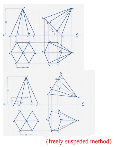
OBLIQUE PROJECTION The word oblique means slanting There are three axes-vertical horizontal and oblique. When a solid is freely suspended from a corner then line joining point of.
Projection Of Solids And Section Of Solids
Draw development of entire solid.

. 1 McGraw-Hill Education PROJECTIONS OF SOLIDS Any object having definite length width and height is called a solid. An Isometric Projection is one type of pictorial projection in which the three dimensions of a solid are not only shown in one view but also their dimension can be scaled from this drawing. H H2 H4 GROUP A SOLIDS Cylinder Prisms GROUP B SOLIDS Cone Pyramids CG CG IMPORTANT NOTE.
It is completely bounded by surfaces which are plane or curved. Solid is 3 dimensional object having lengthbreadth and thickness. PRACTICE PRO BLEMS FOR ENG INEERING DRAW ING I.
Projections of spheres 1 Spheres in contact with each other. 32 Full PDFs related to this paper. He knowledge as well as skill of engineering drawing is essential for.
FIGURE PART OR LOCAL SECTIONS Part at a to detail of type u normal the maln m drawings in this THE FULL SECTIONAL VIEW the d FIGURE 310 ALIGNED SECTIONS In to detail a plane a is 12 an eric of a which cut and apart. Draw projection of the solids showing the curves of inter section between the solids. Group A Solids having top and base of same shape Cylinder Prisms Triangular Square Pentagonal Hexagonal Cube Triangular Square Pentagonal Hexagonal Cone.
Hexa means six and hedron means taces. So cube has 6 faces which are all. Dhananjay A Jolhe Engineering drawing TMH 2008.
720 16 33000 About the book CoNteNt The book provides all aspects and detailed study of Engineering Drawing Plane and 1. Paperback with Four color Jacket Cover Pages. Projection of solids in engineering drawing pdf Nail artwork evokes Every person.
It may be completed. Solids A 3-D object having length breadth and thickness and bounded by surfaces which may be either plane or. ENGINEERING GRAPHICS UNIT III PROJECTION OF SOLIDS.
Draw section lines in it. Projections of solids with axes inclined to both the HP. Draw x1y1 to sec.
File Type PDF Engineering Graphics 1st Year Projection Of Solids performed. K Venugpoal Engineering Drawing and Graphics 3nd edition New Age International 1998. 2 Use opposite process of drawing auxiliary plane.
Plane Draw projectors on it from cut points. Object may be a point line plane solid machine component or a building. Textbook Of Engineering Drawing Pages 151 200 Flip Pdf Download Fliphtml5 Projection Of Solids Projection Of Solids Projection Of Solids Projection Of Solids And Section Of Solids.
A cylinder of base diameter 30 mm axis is 60 mm is resting centrally on a slab of 60 mm square and thickness 20 mm. In Projection solids the projection should be started with a view in. It is required true shape.
ENGINEERING DRAWING PLANE AND SOLID GE O M ETRY By N. Prisms- These are the solids having top and base of same shape. Types of solids Mainly solids are of three types 1Prisms 2Pyramids 3Solids of revolutions.
1st Angle and 3rd Angle Projections. Engineering Drawing Graphics Using Autocad 3rd Edition The new book Fundamentals of Engineering Drawing for polytechnics. If you are a colorful Lady Youll be able to take up brighter.
2015 Reprint ISBN. Consider the following illustration to project the image of an object on to a plane. Conventions and Projections of Simple Solids.
And axis paralel to VP SolutionA cube is having other namee às Hexahedron. 170 mm 235 mm Binding. Read Book Nd Bhatt Engineering Drawing Projections Of Lines Plane and Solid Geometry Subject Catalog This book provides a detailed study of geometrical drawing through simple and well-explained worked-out examples.
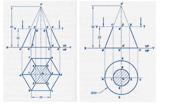
In accordance with the Bureau of Indian Standards BIS SP 46-1988 and IS 696-1972. The study of the projections of a solid is very important in mechanical- design problems. Projection of Solid Section Projection of truncated sphere Procedure 1 1 Let us assume a horizontal plane passing through c 2 Cut on the vertical projector point c with center o with a radius of the horizontal plane.
SOLIDS To understand and remember various solids in this subject properly those are classified arranged in to two major groups. A Point A 20 mm above the HP and 15 mm in front of the VP. R DAHAL MECHANICAL DEPARTMENT Plane Surface A plane may be defined as a surface having length and breadth with negligible thickness.
Projection of Plane Surface and Solids Department of Mechanical Engineering 1112016 BY. PROJECTIONS OF SOLIDS SH1132 Engineering Graphics F. Hey GuysThis is ManasAnd today we gonna talk about projection of solidsIn this video i will make make you familiar with the different types of solids.
10Projection of solids 11Auxiliary projections 3 12Sections of solids 13Development of surfaces 14Intersections of solids 15Isometric projections. The book is divided into seven modules. In engineering drawing practice two principal planes are used to get the projection of object as shown in figure.
For 1 yr polytechnic students of all states of India. The knowledge of projections of solids is essential in 3D modeling and animation. It is designed for first-year engineering students of all branches.
Projection of Lines Inclined to HP and VP. Positions of CG on axis from base for different solids are shown below. Projection Of Solids In Engineering Drawing Pdf.
Draw the projections wnen the oose s inclined 45 to HP. Projections of Points in 2nd 3rd and 4th Quadrant. Engineering Drawing EDRG101 Lecture 7.
Projection of solids - ENGINEERING DRAWINGGRAPHICS. Projections of Sollds 28 Engineering Drawing 2-22 Projection of Hexahedron Cube xample 27A cube of 30 mm side is resting on one of its corner on the HP. Engineering Drawing Lecture 10 29082011 1 Projection of Solids Indian Institute of Technology Guwahati Guwahati 781039.
The book provides all aspects and detailed study of Engineering Drawing Plane and Solid Geometry a core subject for all branches of Engineering study presented in a lucid manner. Draw the isometric projection of the combination of the solids. Draw the projections of the following points.
Procedure 2 1 Diameter of the circle in true view is a g. Mark distances of points of Sectioned part from Tv on above projectors from x1y1 and join in sequence. Make rmaining part of solid dark.
32 Drawing sectional views In orthogonal to complete of an ng Intemally of a The of C line to Nhlch it The of a lire type A.
Projection Of Solids And Section Of Solids

Projection Of Solids

Projections Of Solids Engineering Graphics

Projection Of Solids

Projections Of Solids Springerlink

Gate Ese Projections Of Solids Solid Of Revolution In Hindi P 5 Example Offered By Unacademy
Projection Of Solids

Projection Of Solids Problem 1 In Autocad Youtube
0 comments
Post a Comment